
Vertical Section (VS) is a directional measurement used throughout ZoneVu to position the wellbore within a defined 2D reference plane. It provides a consistent way to represent the well's horizontal progress in a chosen direction and is central to geosteering, cross‑sections, and type‑well alignment workflows. ZoneVu follows the industry‑standard method for computing VS and calculates it relative to whichever VS Azimuth you supply.
What is Vertical Section?
Vertical Section is the projected horizontal distance of a wellbore point onto a directional reference line. This line:
Originates at the Surface Hole Location (SHL), and
Extends outward at a user‑defined VS Azimuth.
Based on this reference:
Movement in the direction of the VS Azimuth → positive VS
Movement opposite the azimuth → negative VS
The SHL always has a VS value of 0 ft
VS does not represent true horizontal displacement; instead, it shows how far the well has progressed in the specific direction defined by the azimuth.
How ZoneVu Calculates Vertical Section
ZoneVu uses the standard projection formula to compute VS from survey data. For each survey station, ZoneVu calculates the cumulative:
North displacement (dN)
East displacement (dE)
Then applies the VS Azimuth (θ) to project these values:
VS = (dN ⋅ cosθ) + (dE ⋅ sinθ)
dN = cumulative North displacement from the SHL
dE = cumulative East displacement
θ = VS Azimuth (degrees; internally converted to radians)
This projection gives a single directional horizontal value representing the well’s position within the Vertical Section Plane.
Where to Add the VS Azimuth
You can manually input a well’s Vertical Section Azimuth in two locations:
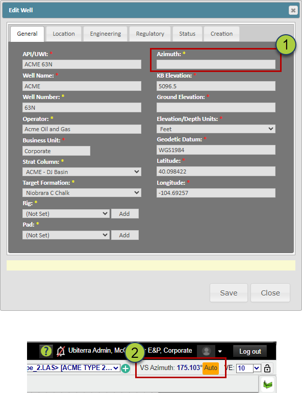
Well Header – The Azimuth input on the General tab.
2D Viewer – Within the View Settings or Well Display Options, where you can override the default azimuth for visualization and interpretation alignment.
How ZoneVu Automatically Calculates the VS Azimuth
If no Vertical Section Azimuth is provided, ZoneVu automatically calculates one by using the azimuth from the SHL to the BHL:
If an Active Plan exists → ZoneVu uses the SHL → BHL azimuth of the Plan.
If no Active Plan exists → ZoneVu uses the SHL → BHL azimuth of the Actual Survey.
This automatically selected azimuth defines the Vertical Section Plane and is used to compute all VS values. Users can override it at any time if a different reference direction is preferred.
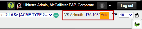
If ZoneVu is using an auto-calculated VS Azimuth, there will be an orange 'Auto' label next to the VS Azimuth in the 2D Viewer.
How VS Changes with Different Azimuths
Because Vertical Section is a projection, the calculated VS value for the same physical point will change if the VS Azimuth changes. Rotating the azimuth rotates the reference plane; the wellbore is then projected onto a different direction, which produces different VS numbers.
Nothing about the well’s location changes—only the projection direction.
Schematic Examples
These diagrams illustrate how the same point on the wellbore maps to different VS values depending on the VS Azimuth.
Image 1 — VS Azimuth = 90°
The red dot maps to approximately 3,000 ft VS
Projection follows the 90° plane
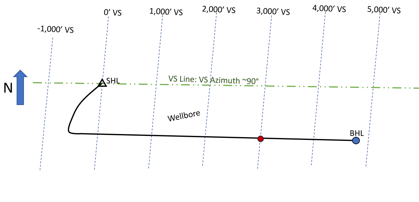
Image 2 — VS Azimuth = 100°
The azimuth reference line is rotated 10°
The same point now projects to about 3,100 ft VS
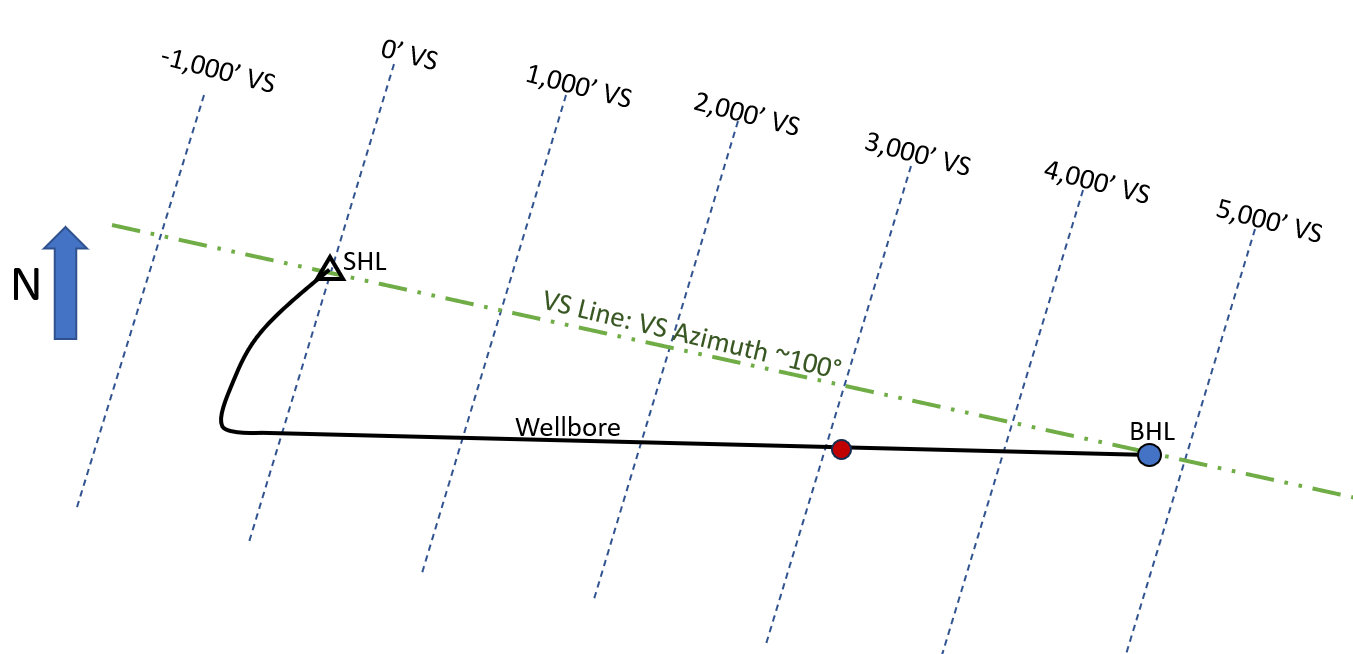
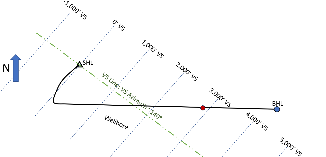
Image 3 — VS Azimuth ≈ 140°
The azimuth reference line has a larger rotation (~50° from 90°)
The same point now projects to roughly 2,900 ft VS
These differences result solely from the orientation of the projection plane, not a change in the wellbore's location.