
Creating a Geosteering Interpretation
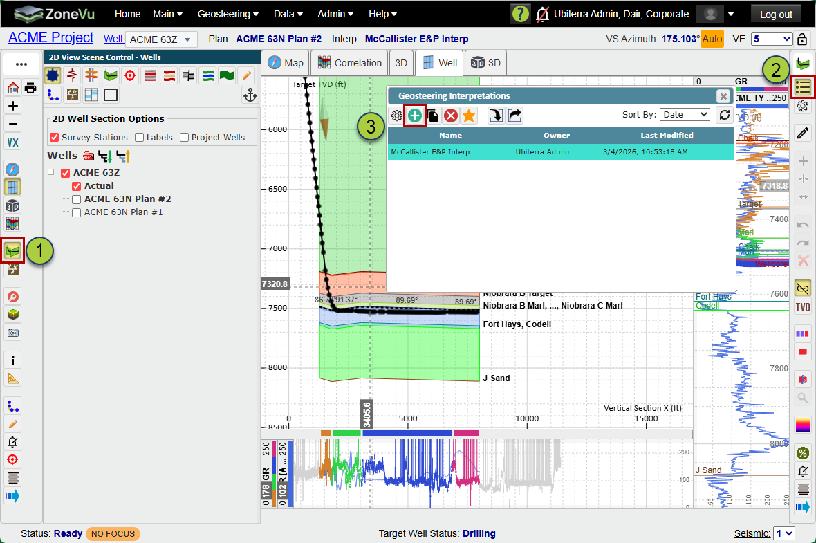
Click the 'Geosteering' button in the lefthand button menu to activate the 'Geosteering Module' and open the 'Geosteering Buton Tree'
Click the 'Geosteering interpretations list' button near the top of the 'Geosteering Buton Tree' to open the 'Geosteering Interpretations ' dialog
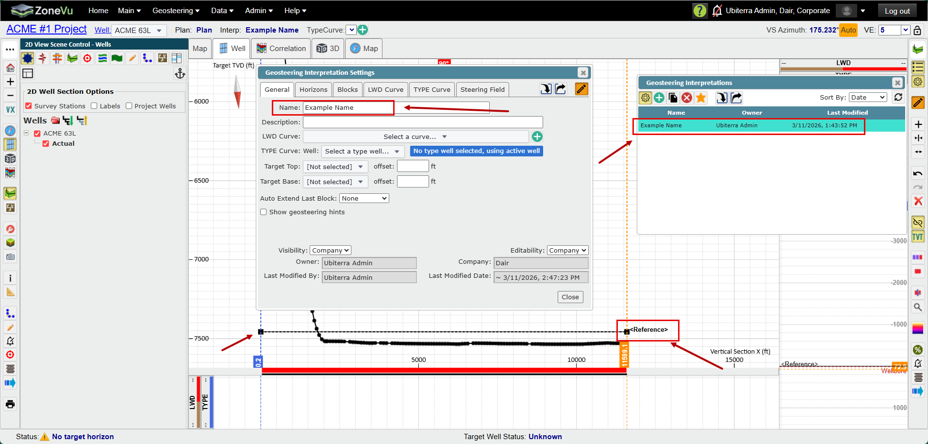
Click the 'Create' button to open the 'Geosteering interpretation Settings' dialog
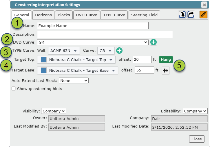
From the 'Geosteering interpretation Settings' dialog
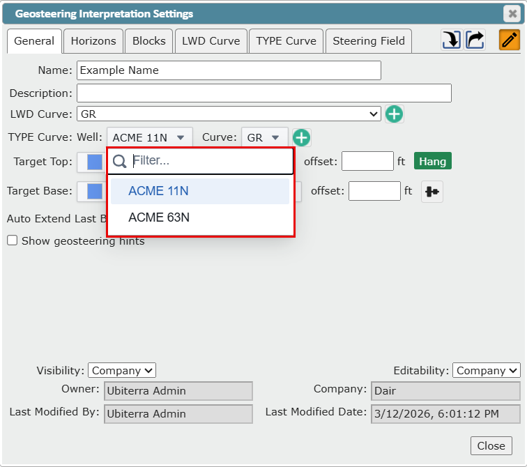
Give the new geosteering interpretation a name
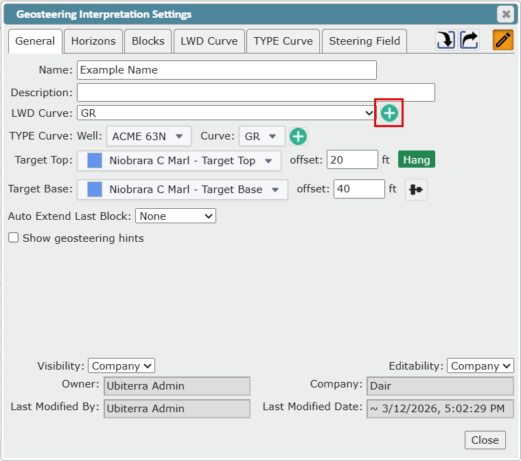
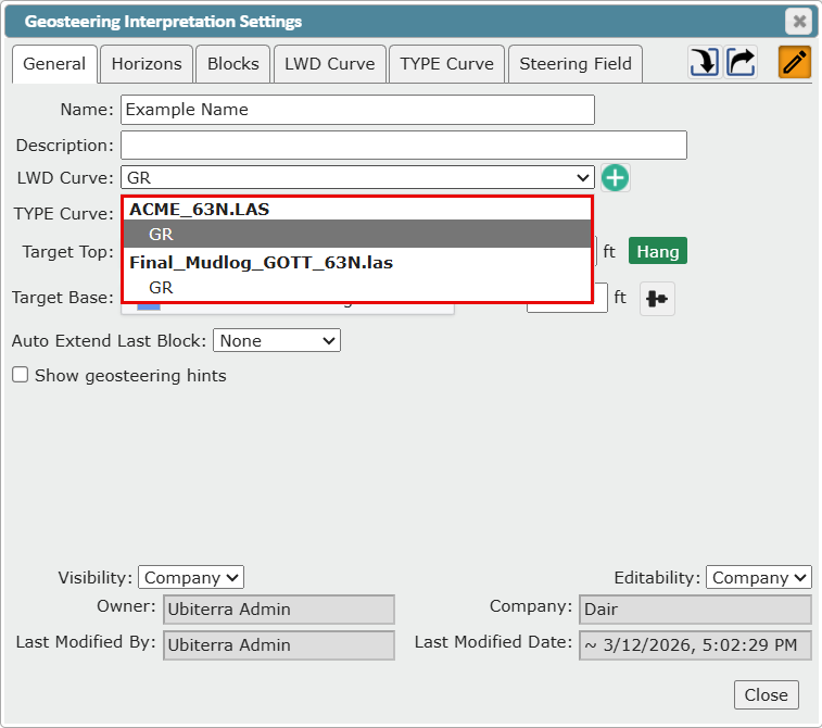
Select a logging while drilling curve from the 'LWD Curve' drop-down
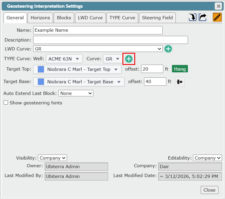
Select a Type Curve - Choose a well from the 'Type Curve: Well' drop-down and a curve from the 'Type Curve: Curve' drop-down
Select a 'Target Top' and 'Target Base' to set a target zone.
Note: A target zone may be defined by a 'Target Top' only, or by both a 'Target Top' and a 'Target Base'.
Note: Use the 'offset' drop-downs to define a target zone that does not begin and end directly on formation tops
Select a 0 TVT 'Hang' location at the top or base of the 'Target Zone'
Note: By default, the 'Hang' location will be located at the 'Target Top', but can be moved to the 'Target Base' by clicking the 'Hang' button
 to the right of the 'Target Base'.
Choose an option to 'Auto Extend Late Block'
None: The last geosteering block will not extent with new data
Last Station: The last geosteering block will automatically extend to the last survey station
Hole Depth: The last geosteering block will automatically extend to the deepest hole depth
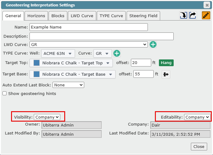
Geosteering Interpretation Visibility and Editability Settings
Set the Geosteering Interpretation 'Visibility'
All: Anyone who has access to this Well can view the interpretation
Company: Only users logging into the same 'ZoneVu' company account can view the interpretation
Owner: Only the Creator can view the interpretation
Set the Geosteering Interpretation 'Editability' (does not have to match the Visibility Setting)
All: Anyone who has access to this well can edit this interpretation
Company: Only users logging into the same 'ZoneVu' company account can edit this interpretation
Owner: Only the creator can edit this interpretation
Locked: The interpretation cannot be changed until the 'Editability' setting is changed to another state
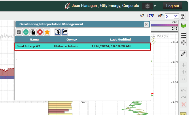
The newly created interpretation will now appear in the 'Geosteering Interpretation List' and the Geosteering Interpretation will be displayed in the Cross-Section
Target Zone Definition
A drilling 'Target Zone' may be defined by a 'Target Top' only, or by both a 'Target Top' and a 'Target Base'. If only a 'Target Top' is assigned, then anything below that 'Target Top' will be considered 'in zone' (Using the Percent in Zone Calculator). If both a 'Target Top' and 'Target Base' are assigned, "in zone' will be between them.
'Target Zone' selection drop-downs: the drop-down menus for selecting Target Tops' and Target Bases' will show a list of formations available in the associated 'Strat Column'. If there is a red star next to the formation name, it means that the formation does not have a top picked in the 'Type Well' you have selected. You can pick tops on 'Type Wells' either the '2D viewer' or the 'Correlation Panel'. See articles below:
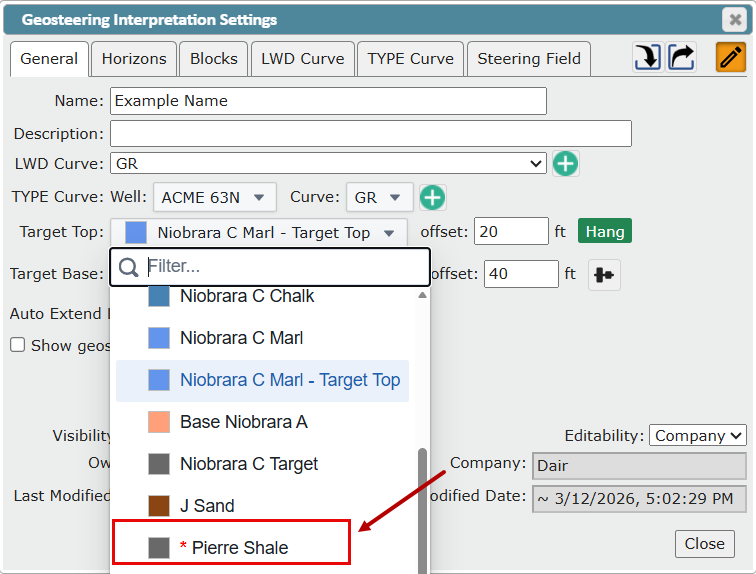
Target Zone Offset: Use the 'offset' drop-downs to define a 'Target Zone' that does not begin and end directly on a formation top. This means you are not required to have a formation named "Target Top" or "Target Base" in your 'Strat Column' or tops of the same name picked on your type well. Positive values will shift the target deeper and negative values with shift the target line shallower
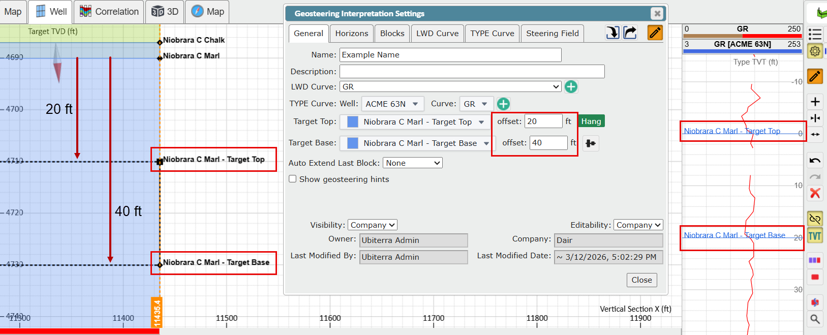
Once a 'Target Zone' has been defined, it will be displayed in the '2D Viewer' cross-section as two labeled dashed lines, as well as in the verticals track with labeled solid lines.
Geosteering Interpretation Minimum Requirement
A name is the only element required to create a geosteering interpretation. Once you have given an interpretation a name it is created and will appear in the 'Geosteering Interpretations List'.
If the 'Active Well' does not have tops, a single reference horizon will be generated and can be manipulated like any 'Geosteering Horizon'.
If the 'Active Well' has 'Tops' then they will be used to generate geosteering horizons. If a 'Type Well' curve is added, then the 'Type Well' curve tops will replace the active well tops and update the 'Geosteering Horizon' locations.
Adding Multiple LWD Curves to an Interpretation
To add other 'LWD Curves' click the 'Create' button next to the LWD Curve Dropdown
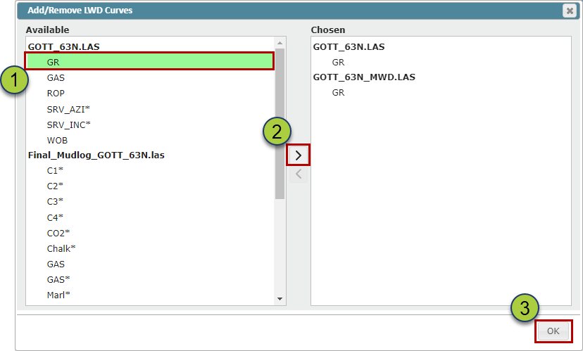
In the 'Add/Remove LWD Curve' dialog box, select one or more curves to add
Note: You can add curves from any .LAS or LWD log
Click the '>' button to move the selected curves to the "Chosen" list
Click the 'OK' button to finalize the curve selection
The additional logs will now appear in the 'LWD Curve' dropdown
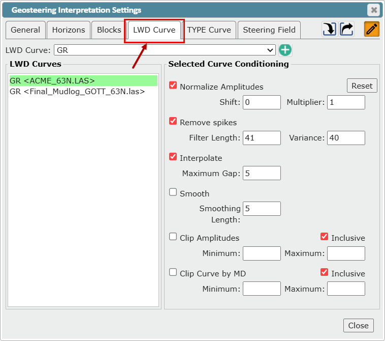
You can also add, change, edit, and condition the LWD curve in the 'LWD Curve' tab of the 'Geosteering Interpretation Setting' dialog.
Adding Multiple Type Well Curves to and Interpretation
To add multiple type curves, click the 'Create' button next to the 'Type Curve' dropdown
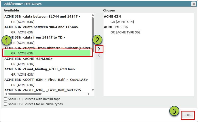
In the 'Add/Remove Type Curves' dialog, select one or more curves to add
Click the '>' button to move the selected curves to the "Chosen" list
Click the 'OK' button to finalize the curve selection
Can't find a Curve?
You can add curves from any well with a top pick for the active well's assigned target formation. ZoneVu uses the target formation top to hang curves from different wells in the 'Vertical Log Tracks'. To see other curves use the below check box options at the bottom of the 'Add/Remove Type Curves' dialog.
'Show TYPE curves with invalid tops' checkbox: When checked, wells missing a top pick for the assigned target formation will be listed in the "Available" column
'Show TYPE curves for all Curve Types' checkbox: When checked, all Log curves will be listed in the "Available" column
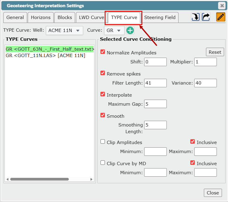
The additional wells and/or logs will now appear in the 'Type Curve: Well' and/or 'Type Curve: Curve' dropdowns.
These two dropdowns can be used to select the active type well and curve this interpretation.
You can also switch 'Type Wells' and assign type wells to individual geosteering blocks in the '2D Cross-Section'. See the related article to learn more. (Adding Multiple Type Logs to a Geosteering Interpretation)
Controlling/Editing Geosteering Horizons used in Cross-Section
Also see Creating and Editing Geosteering Horizons
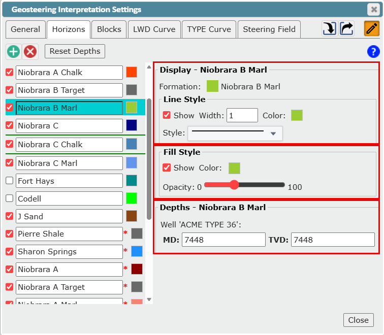
Geosteering horizons are generated by checking each 'Top' on the interpretation's initial 'Type Well' against the 'Strat Column's' list of 'Formation Names'. If a 'Top' from the 'Type Well' has a 'Formation' name match, then a 'Geosteering Horizon' is created in the 'Geosteering Interpretation'. To control which 'Geosteering Horizons' are used in the 'Geosteering Interpretation Cross-Section' and their display properties, go to the 'Horizons' tab of the 'Geosteering Interpretation Settings' dialog.
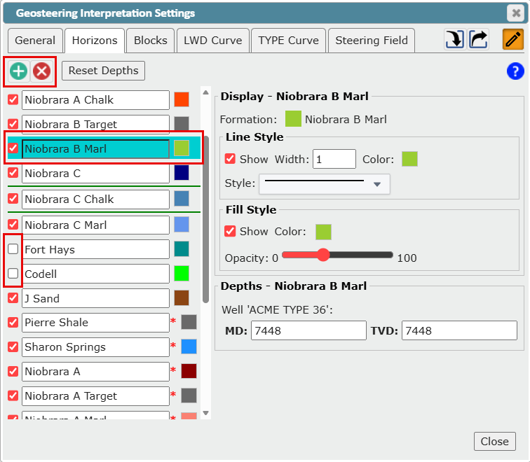
Hide Geosteering Horizons: To hide an interpretation's 'Geosteering Horizons', uncheck the box next to the 'Geosteering Horizon' name in the list.
Remove Geosteering Horizons: To remove a 'Geosteering Horizon' from an interpretation, select the 'Geosteering Horizon' name from the list and click the 'Delete' button at the top. This will remove the 'Geosteering Horizon' from this interpretation, but will not delete the associated 'Type Well Top' from the 'Type Well'. The deleted horizons can be readded. See 'Add Geosteering Horizons'.
Add Geosteering Horizons: To add one or more horizons to an interpretation, click the 'Create' button to open the 'Add Horizons' dialog.
From the 'Add Horizons' dialog box, select one or more curves to add
Click the 'OK' button to finalize the Tops selection
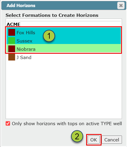
Note: Only formations associated with active 'Type Well Tops' will be displayed. Uncheck the 'Only show horizons on active Type well' checkbox to list all formations from the associated 'Strat Column'
The additional horizons will now be listed on the 'Horizons' tab of the 'Geosteering Interpretation Settings' dialog, ordered by depth. By default, a horizon's color is defined by the associated 'Strat Column'. You can change the horizon's display settings for this geosteering interpretation from the 'Display' and 'Fill Style' sections of the 'Horizons' tab. You can change the horizon's depth for this geosteering interpretation from the 'Depth' section of the 'Horizons' tab.
DisplayingGeosteering Interpretation Target Zones in the Background
If a geosteering Interpretation has only a 'Target Top' defined, when it is displayed in the background of another interpretation, it will appear as a dashed line. If both a 'Target Top' and 'Target Base' are defined the target zone will be displayed as a filled polygon.
Example: In the image below Interpretation #5 (purple) & Interpretation #4 (orange) has been turned on in the background of the active interpretation (Interpretation #2: blue). Since #5 has only a 'Target Top' defined it is being rendered as a purple-dashed line. #4 has both a 'Target Top' and 'Target Base' defined and is rendered as a polygon.
