Hotkeys:
Viewer "Alt" Keyboard Shortcuts:
Alt + “+”: Zoom In
Alt + “-“: Zoom Out
Alt + Z: Switch Viewers (Map, 2D, 3D, Correlation Panel)
Alt + Q: Opens Display Settings Pop-Up
Alt + A: Opens Scene Control
Alt + I: Opens Scene Info Pop-Up
Alt + X: Opens Scene Snapshot
Alt + S: Opens Measuring Tool
Alt + G: Opens the Geosteering Module
Alt + B: Wellbore Modification Tool
Alt + C: Completions Module
Alt + H: VX/MD Horizontal Scale
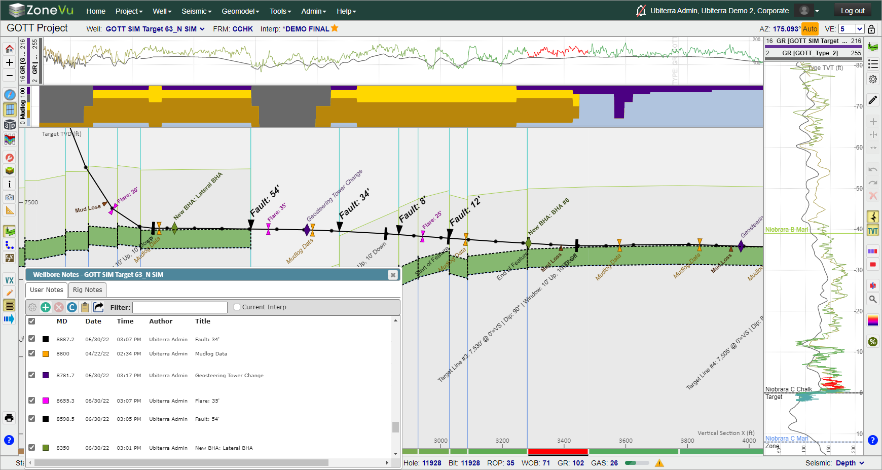
Alt + W: Opens Wellbore Notes
Alt + M: Opens the Manual Drilling Update Pop-Up
Alt + R: Opens the Report Generator
Geosteering Hotkeys:
Alt + E: Toggle Geosteering Edit Mode On/Off
CTRL + left mouse button: creates a new geosteering interpretation block for interpretation
Double Left mouse click over a Geosteering Interpretation Block: Activates the Geosteering Interpretation Block (You must be in Active Edit Geosteering Mode)
Right & Left Arrow: With a Geosteering Block selected, each arrow key click will move to the neighboring Geosteering Block in that direction
With the cursor over the Cross-Section:
CTRL + left mouse button: creates a new geosteering interpretation block for interpretation
SHIFT + scroll mouse: Change vertical exaggeration
Right mouse clicks over black diamond at start/stop of strat block: Brings up the dropdown menu for various tasks including add a block, hide blocks, etc. Also allows you to create/remove a fault.
With the cursor over a Log Track:
CTRL + left mouse button: creates a new geosteering interpretation block for interpretation
SHIFT + left mouse hold: adjust the scaling of all log curves in the track
Scroll Mouse Wheel at the center of the Log Header: Expands or contracts the Min/Max log scale
Moving the ZoneVu 3D Viewer
Pan: Shift + Left Mouse Button – Pan the 3D cube right/left or forward/back along the main horizontal plane
Pan Up: Shift + CTRL + Left Mouse Button - Pan the 3D cube up/down
CTRL + Left Mouse Button On Seismic Line: Changes the displayed seismic Line (Inline, Crossline, Depth Slice)
Correlation Panel Hotkeys:
Alt + E: Toggle Top Edit Mode On/Off
CTRL + Left mouse click: Pick selected top a Well
Main Viewer Button Tree:
Home View button: The scene display zooms to bring the whole Well into view

Zoom In button: Zooms the display in

Zoom Out button: Zooms the display out

Map Viewer button: Switches to the Map Viewer

2D Viewer button: Switches to the 2D Viewer (Current View)

3D Viewer button: Switches to the 3D Viewer

Correlation Panel button: Switched to the Correlation Panel Viewer

Display Settings button: Launches the Display Settings pop-up

Scene Control button: Launches the Scene Control pop-up. Scene Control is used to select entities to be displayed in the scene like curves, wells, surfaces, etc. (Related Articles: Using the Scene Control in the 2D Viewer, Using the Scene Control in the 3D Viewer, Using the Scene Control in the Map Viewer)

Scene Info button: Launches the Scene Info pop-up. Displays the locational info of the cursor, the last Survey Station loaded, and the selected Geosteering Block

Snapshot button: Launches the Scene Snapshot pop-up. Snapshots are saved display settings (Related Article: Using the Scene Snapshot)

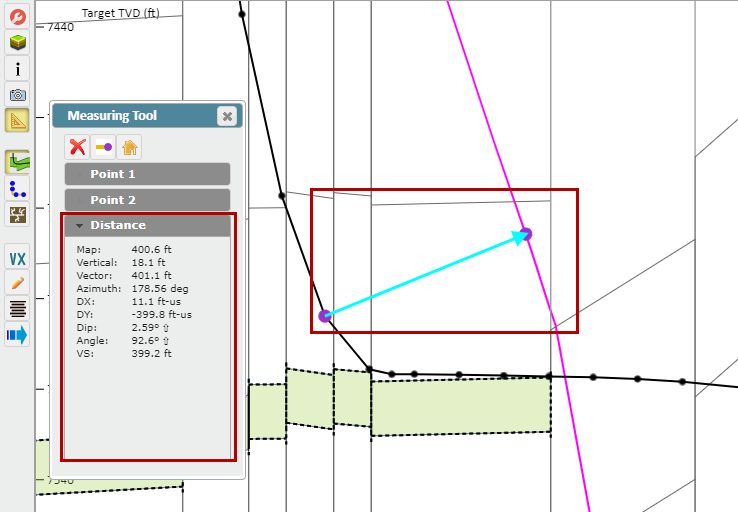
Measuring Tool button: Launches the Measuring Tool pop-up. Measures between any two points in the 2D, 3D, or Map Viewers (Related Article: How to use the Measuring Tool)

Geosteering Module button: Launches the Geosteering Module. The Geosteering Button Tree will appear in a right-hand toolbar

Wellbore Modification button: Launches the Wellbore Modification Module. The Wellbore Modification Button Tree will appear in a right-hand toolbar. Create points from the existing Well Plan or Actual for proposed modifications or create a Target Line and Drilling Window (Related Articles: Creating Target Lines in ZoneVu, Modifying Well Plans in ZoneVu)

Completions Module button: Launches the Completions Module. The Completions Modification Button Tree will appear in a right-hand toolbar. Create, plan, and/or analyze completions jobs (Related Article: Creating and Loading Frac data into ZoneVu)

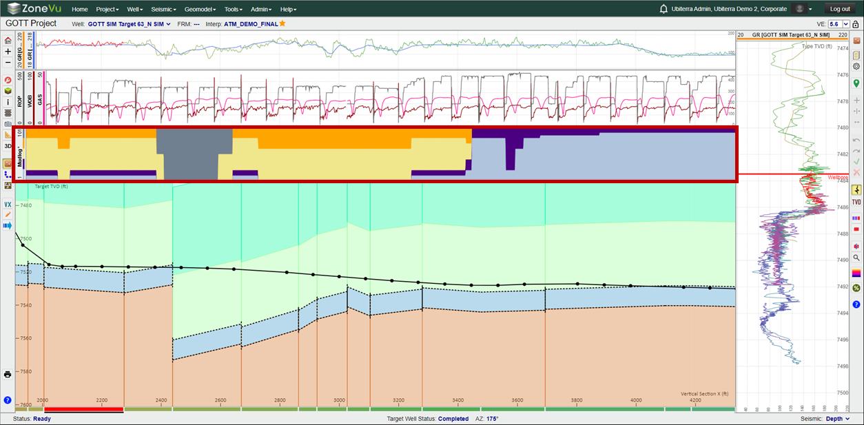
VX button: Switches between VX and MD mode. Note: if VX is shown, the view is currently in VX mode

MD button: Switches between VX and MD mode. Note: if MD is shown, the view is currently in MD mode

Manage Drawings button: Launches the Manage Drawings pop-up.

ZoneVu Alerts Button: Opens up the ZoneVu Alerts Dialog

Wellbore Notes button: Launches the Wellbore Note pop-up. Create, sort, and display User Notes along the Active Wellbore. The Drilling Notes come directly from the drilling well via RigStream (Related Article: Creating User Notes in ZoneVu)

Manual Drilling Update button: Launches the Manual Drilling Update pop-up. Manual Drilling Updates are used to load new Surveys and/or Logs. This is for wells that are not being updated via RigStream (Related Article: Manual Dilling Updates)

Print Layout button: Launches the Print Layout Viewer

Common Workflows in the Viewers:
Zooming - Use the mouse wheel or the "+/-" buttons on the left-hand toolbar
Opening the Project Folder in a Separate Tab - Click on the "Project Name" in the upper-left corner of the grey toolbar. This is a hyperlink that will open the Project's Folder in a separate tab

Opening the Well Folder in a Separate Tab - Click on the text "Well:" next to the Active Well dropdown in the upper-left corner of the grey toolbar. This is a hyperlink that will open the Well's Folder in a separate tab

Moving around in the 3D Viewer
Rotate: The 3D scene can be rotated by depressing the left mouse button and moving the mouse
Zoom: To Zoom the 3D scene in and out roll the mouse wheel or use the "+/-" buttons located at the top of the lefthand toolbar
Pan: Shift + Left Mouse Button – Panning is accomplished by holding down the shift key and simultaneously depressing the left mouse button while moving the mouse
Changing the Point of Rotation: By default, the Point of Rotation is at the center of the 3D Cube. To change the Point of Rotation, right-click on any displayed object and select "Center Scene Here"
Move Seismic Line: CTRL + Left Mouse Button – to move an inline, crossline, or depth slice hold down the control key while simultaneously depressing the left mouse button and dragging the displayed seismic line/slice to the desired position. If the scene control is open, the line number will be updated to the current position of the cursor as it is moved
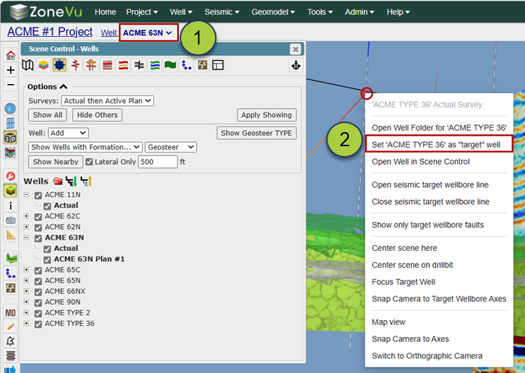
Selecting an Active Well - There are three ways you can make a Well the Active Well
Using the "Well" dropdown on the upper grey menu bar, or
Right-clicking on a visible Well in the Viewer and selecting "Set Active Wellbore
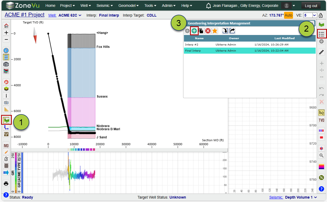
Creating a Geosteering Interpretation -
Open the Geosteering Interpretation module
Open the Geosteering List
Click the green "+" button to open the Create a New Geosteering Interpretation dialog box, fill out the required information, and click the "OK" button to create the new Geosteering interpretation. (Related Article: Creating a Geosteering Interpretation)
Note: Use "Alt + E" to toggle Edit Geosteering Mode On/Off
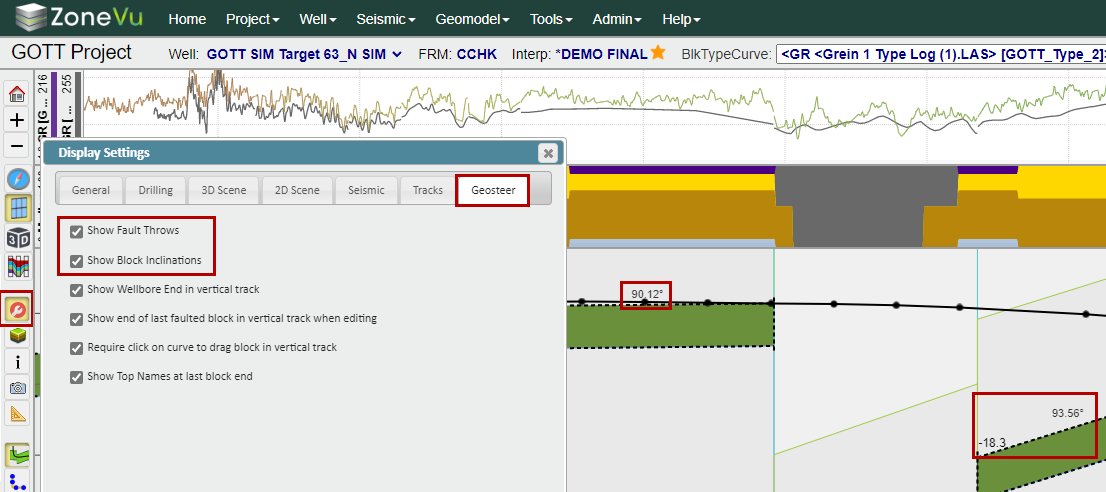
Turning On/Off Block Inclination & Fault Throw Labels - Open the "Display Settings", select the "Geosteer" tab, and use the "Show Fault Throws" & "Show Block Inclinations" checkboxes to control the Fault Throw and Block Inclination labels in the Cross-Section.
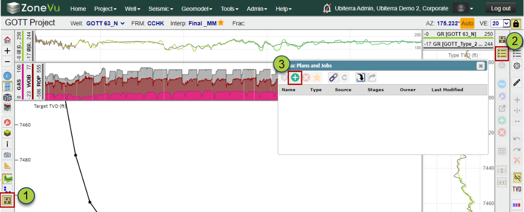
Creating a new Frac -
Open the ZoneVu Frac module
Open the Frac List
Click the green "+" button to open the Create a Frac dialog box, fill out the required information, and click the "OK" button to create the new Frac. (Related Article: Creating and Loading Frac data into ZoneVu)
Make a Snapshot - Click the "Snapshots" button to open the "Snapshots" dialog box. Use the "Create New" button to name and save a new snapshot of the currently showing scene. All view settings will be saved as part of that snapshot. Snapshots are shared, so other people accessing the project can use them. (Related Article: Using the Scene Snapshot)
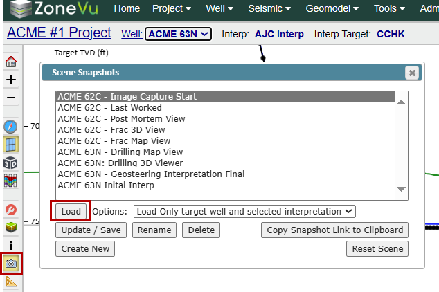
Loading a Snapshot - Click the "Snapshots" button to open the "Snapshots" dialog box. Select a previously saved Snapshot and click the "Load" button to load the scene to that snapshot. (Related Article: Using the Scene Snapshot)
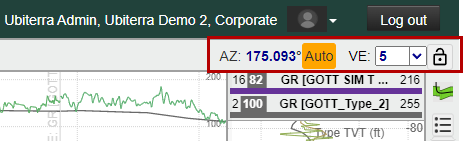
Setting the Vertical Exaggeration & Wellbore Azimuth for the 2D Viewer - In the upper-right corner of the 2D Viewer, you can set the Azimuth used to calculate the Wellbore's Vertical Section, set the vertical exaggeration, and lock the vertical exaggeration settings.
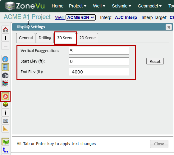
Setting the Vertical Exaggeration & rendering depths for the 3D Viewer - Open the "Displays Settings" dialog box, select the "3D Scene" tab, and use the Vertical Exaggeration, Start Elevation, and End Elevation inputs to control what depths the 3D cube is drawn at and the vertical exaggeration.
Measuring - Click the 'Measuring Tool' button. Click on an object in the scene to add a measurement point. Select the "Point 2" tab and click on an object in the scene to add a second measurement point. Select the "Distance" tab to see related data. (Related Article: How to use the Measuring Tool)
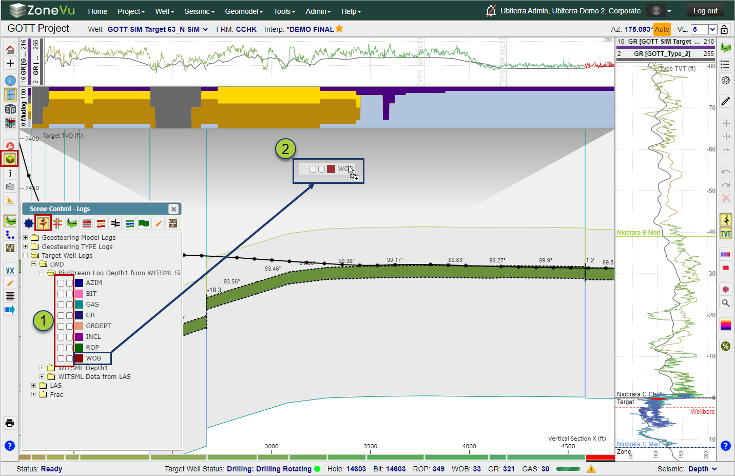
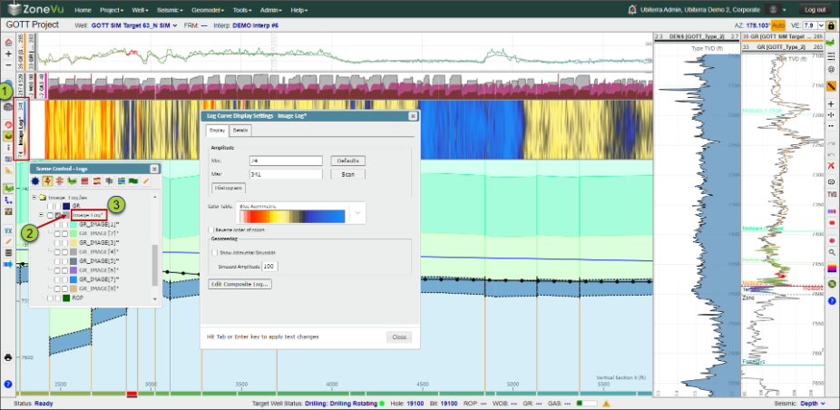
Displaying Log Curves - Open Scene Control and navigate to the "Logs" tab. Scroll down to find the LAS file and Log Curve you wish to display. There are two ways to display a Log Curve in a Log Track
Click one of the checkboxes next to the Log Curve (Left Checkbox = Vertical Log Track, Right Checkbox = Horizontal Log Track)
Click and drag the Curve Name and drop it onto an existing Log track or into a new Log Track. (Related Article: Working with logs in the 2D Viewer)
Connecting the Active Well to RigStream - Select "RigStream Connection" under the "Well" dropdown. Click the "Connect RigStream Well" button, use the "RigStream Configuration" dropdown to select a WITSML Vendor, select the related Well Channel in the Well List, click the "OK" button, than navigate to the "Logs" tab and set the GR Tool Setback. (Related Article: Setting up RigStream on the Target Well)
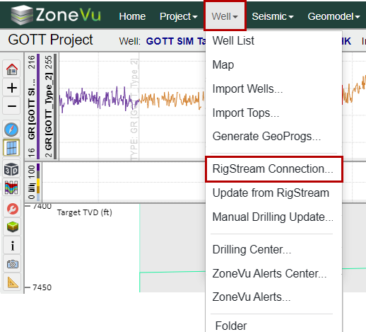
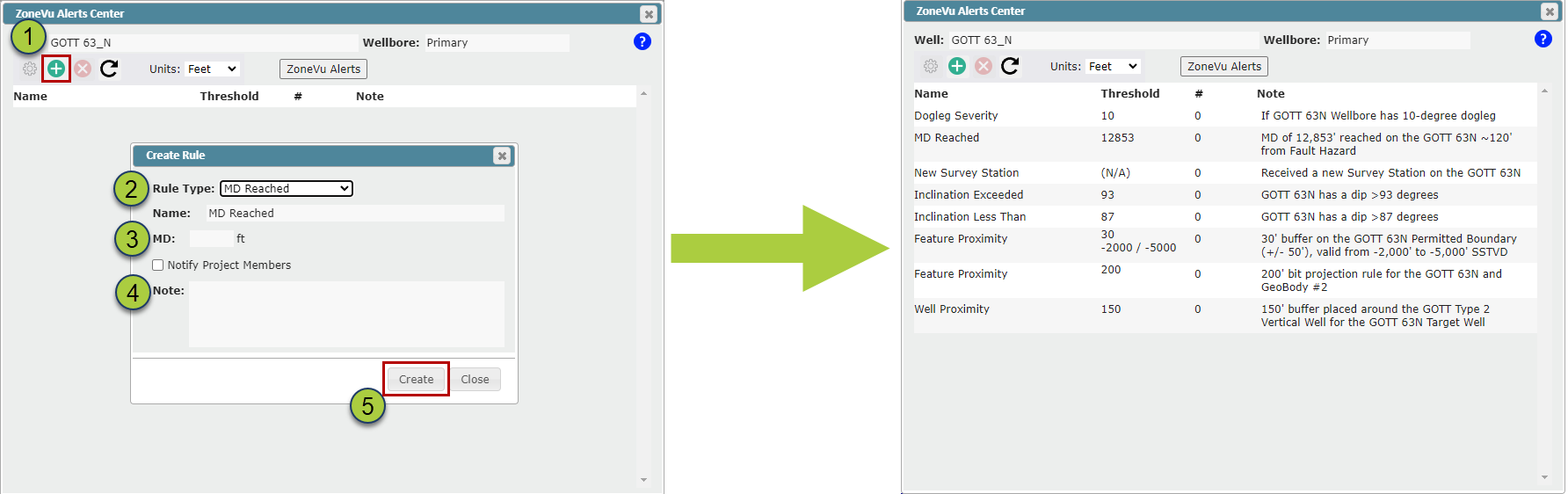
Creating a ZoneVu Alert - Select "ZoneVu Alerts Center" under the "Well" dropdown. Click the green "+" button to create a new ZoneVu Alert Rule, select the appropriate rule, fill out the required info, and click the "OK" button to create the ZoneVu Alert Rule (Related Article: How to set up ZoneVu Alerts)
Creating a User Note - Right-click in the Cross-Section where you want to place the User Note, select "Create User Note", fill out the required info, and click the "OK" button to create the User Note (Related Article: Creating User Notes in ZoneVu)
Creating a Litho Log - ZoneVu can create a Litho Log from a LAS file. See the related article for an in-depth walkthrough: Importing and Displaying Mudlog Data
Creating an Image Log - ZoneVu can create an Image Log from Azimuthal Gamma-Ray data. See the related article for an in-depth walkthrough: How to load and view Azimuthal GR data
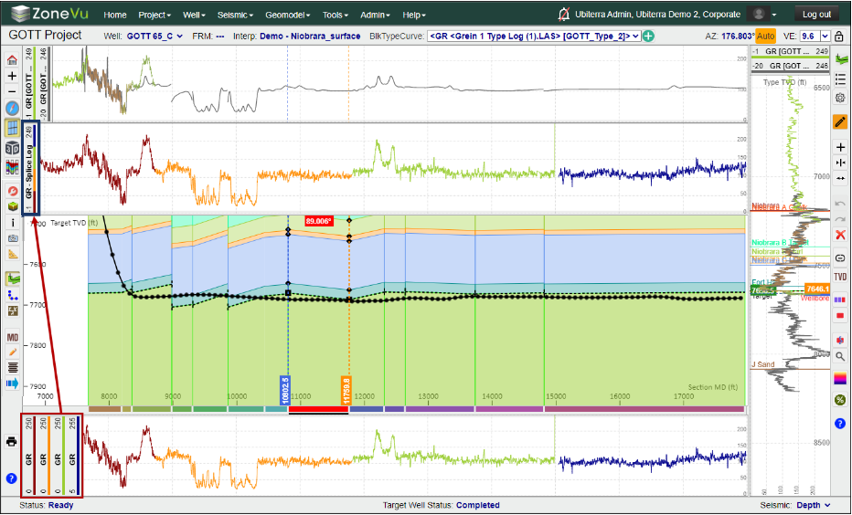
Creating a Splice Log - ZoneVu's Splice Log tool allows you to splice together and normalize two or more Log Curves to use as a single curve. See the related article for an in-depth walkthrough: Creating a Spliced Log in ZoneVu