
These videos and tutorials will show you how to properly set up a project including setting the stratigraphic column, setting up RigStream, adding new Users, loading seismic data, creating, and editing wells, and creating geomodels.
Intro and homepage navigation – The following video will help you navigate the homepage in ZoneVu. To begin go to https://zonevu.ubiterra.com and enter your login information.
Setting up RigStream – These articles and videos will walk you through the steps of setting up your RigStream connections and troubleshooting RigStream.
Setting up your initial stratigraphic column in ZoneVu - Before adding wells in a project, you must define a stratigraphic column for the area. This stratigraphic column can be used for all wells in the project (or multiple projects).
Create and Edit Wells – These videos will show you how to create your initial wells in the project.
Loading Layer Files – This How-To will show you how to load layer files and edit their display properties
Creating Geomodels – This video will show you how to set up a geomodel, add control point sets and grids, and convert them into surfaces and zones for display in ZoneVu’s 2D and 3D viewers.
Loading Seismic Data – This How-To article will walk you through the process of loading seismic volumes, horizons, and faults.
Creating and Setting up a Project – This video will show you how to build a populate a project.
ZoneVu Mobile Viewer – This How-To article will show you how to access and use the ZoneVu Mobile Viewer (https://zonevu.ubiterra.com/mobile)
See the complete list of Knowledge Base Articles at the end of this document for more information.
Interpreting a Well
Once your project has been properly set up and you have imported your type log and horizontal well, you can open the project and build your geosteering interpretation. To return to the main menu, click the ZoneVu logo in the top left corner of the screen or the Home button.
Click Projects. You can also click Projects on the green menu bar.
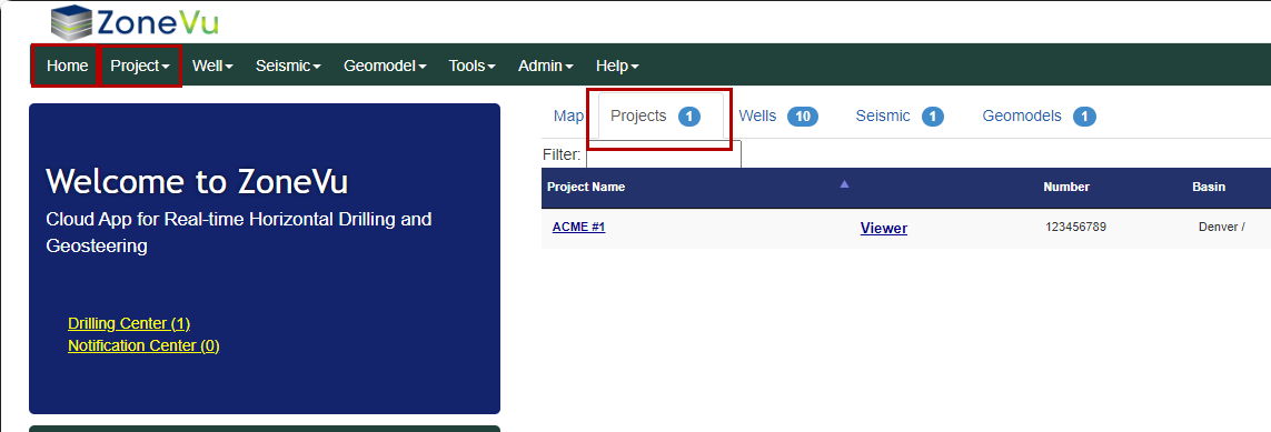
Click the name of the project that you wish to open. This will bring you to the Project folder, which contains a list of all of the wells, seismic, geomodels, and documents included in that project.
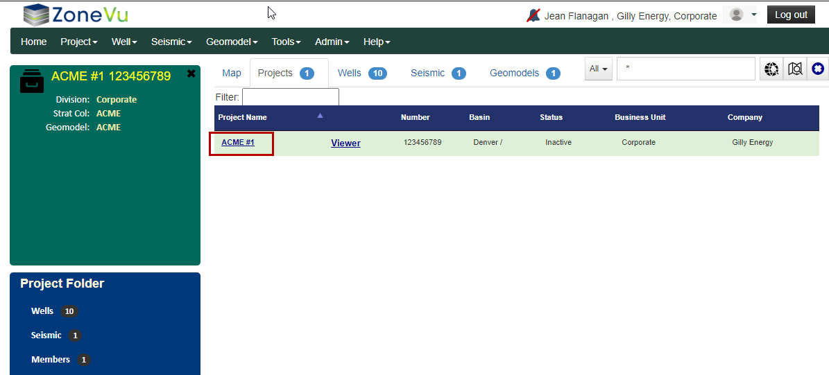
Click Header if you wish to view/modify the header information for the project.
Click on one of the wells in the list if you wish to view/modify individual wells.
Click Viewer in the top right corner if you wish to enter the 3D Viewer, 2D Viewer, or Map Viewer. Note: If you get lost, just click on the ZoneVu icon in the top left corner to return to the main screen.
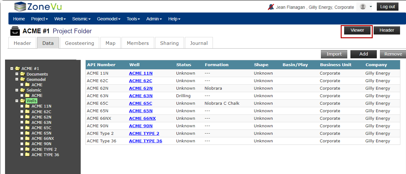
Clicking Viewer will bring you to the 2D Viewer by default, and you can switch to the 3D Viewer or the Map Viewer using the buttons along the left edge of the screen.
If this is your first time in the project, and no wells are displayed, click on the dropdown box next to “Well” in the gray bar at the top of the viewer.
Once you are in the viewer, activate the Geosteering Module by clicking the Geosteering Module button on the left button tree.

3D Viewer - 3D Visualization Module:
Tool Bar on the left side of the Screen:
Home View button: The scene display zooms to bring the whole Well into view

Zoom In button: Zooms the display in

Zoom Out button: Zooms the display out

Map Viewer button: Switches to the Map Viewer

2D Viewer button: Switches to the 2D Viewer (Current View)

3D Viewer button: Switches to the 3D Viewer

Display Settings button: Launches the Display Settings pop-up

Scene Control button: Launches the Scene Control pop-up. Scene Control is used to select entities to be displayed in the scene like curves, wells, surfaces, etc.

Scene Info button: (Currently not available in the 3D Viewer)

Snapshot button: Launches the Scene Snapshot pop-up. Snapshots are a saved view state for the scene

Measuring Tool button: Launches the Measuring Tool pop-up. Measures between any two points in the 2D, 3D, or Map Viewers

Wellbore Modification button: Launches the Wellbore Modification Module. The Wellbore Modification Button Tree will appear in a righthand toolbar. Create points from the existing Well Plan or Actual for proposed modifications or create a Target Line and Drilling Window

ZoneVu Frac button: Launches the ZoneVu Frac. The ZoneVu Frac Button Tree will appear in a righthand toolbar. Create, plan, and/or analyze completions jobs

Drilling Notes button: Launches the Wellbore Note pop-up. Create User Notes along the active Wellbore. The Drilling Notes come directly from the drilling well via RigStream

Manual Drilling Update button: Launches the Manual Drilling Update pop-up. Manual Drilling Updates are used to load new Surveys and/or Logs. This is for Wells that are not being updated via RigStream

Print Layout button: Launches the Print Layout Viewer

Knowledge Base Article button: How to Operate the 2D & 3D GeoViewer in ZoneVu

Moving the ZoneVu 3D Scene
Rotate – the 3D scene can be rotated by depressing the left mouse button and moving the mouse.
Zoom – to Zoom the 3D scene in and out roll the mouse wheel or use the +/- buttons located at the top of the toolbar.
Pan: Shift + Left Mouse Button – Pan the 3D cube right/left or forward/back along the main horizontal plane
Pan Up: Shift + CTRL + Left Mouse Button - Pan the 3D cube up/down
Move Seismic Line – CONTROL + LEFT MOUSE BUTTON – to move an inline, crossline, or depth slice hold down the control key while simultaneously depressing the left mouse button and dragging the displayed seismic line/slice to the desired position. If the scene control is open, the line number will be updated to the current position of the cursor as it is moved.
It is also possible to enter a new inline, crossline, or depth slice number on the scene control to go directly to a new line/slice displayed.
2D Viewer – Geosteering Cross Section Viewer
2D Viewer – This is the main geosteering module
From here you will interpret individual strat blocks to build your interpretation. If it isn’t currently selected, click on the Well Name to the right of the PROJECT NAME and make sure that it says the name of your drilling well. If you wish to interpret other wells in the project, you will use this dropdown.
Buttons on the left side of the screen
These buttons are similar to those in the 3D Viewer. In addition, there is a button to toggle on the Geosteering Module. The Geosteering Module button must be selected to view/create/edit related Geosteering Interpretations. (2D Viewer Scene Control)
In addition:
Scene Info button: Launches the Scene Info pop-up. Displays the locational info of the cursor, the last Survey Station loaded, and the selected Geosteering Block

Geosteering Module button: Launches the Geosteering Module. The Geosteering Button Tree will appear in a righthand toolbar

VX button: Switches between VX and MD mode. Note: if VX is shown, the view is currently in VX mode

MD button: Switches between VX and MD mode. Note: if MD is shown, the view is currently in MD mode

Manage Drawings button: Launches the Manage Drawings pop-up.

Buttons on the right side of the screen:
Geosteering Interpretation Management button: Opens the Geosteering Interpretation Management pop-up. Allowing you to view, select, copy, delete and add Geosteering Interpretations

Geosteering Interpretation Settings button: Opens the Geosteering Interpretation Settings pop-up. Modify the selected Geosteering Interpretation including adding/changing LWD and Type Curves and Tops. You can also apply curve conditioning to the LWD and Type Logs

Edit Geosteering button: This must be selected (orange) if you wish to edit your interpretation. The reason for having this button is so that users don’t accidentally modify someone else’s interpretation while viewing it

Add Block button: This button adds a new strat block to your interpretation. You can also do it using a hotkey (see below)

Normalize Type Curve Shift button: Activate the button, then click and drag the curve to adjust the Type Curve. This normalizes the Type Curve to the LWD. If you wish to shift (bulk/multiply) the LWD, click on the LWD – GR header and either drag left/right to bulk shift, or roll the mouse scroll to multiply. You can also do this manually by following the instructions at the following link: Manually Normalize your LWD to the Type Log

Normalize Type Curve Multiplier button: Activate the button, then click and drag the curve to adjust the Type Curve. This normalizes the Type Curve to the LWD. If you wish to shift (bulk/multiply) the LWD, click on the LWD – GR header and either drag left/right to bulk shift, or roll the mouse scroll to multiply. You can also do this manually by following the instructions at the following link: Manually Normalize your LWD to the Type Log

Undo button: Will undo the last Geosteering Interpretation change made. You can also use CTRL+Z

Redo button: Will redo the last Geosteering Interpretation change that was undone. You can also use CTRL+Y

Delete Top Picks or Block button: Will delete the selected Strat Block or Pick

Coupe/Decouple Cross-Section Vertical Log Track Scaling button: If selected the Cross-Section and Vertical Log Track scales will be decoupled, allowing you to scale them independently

TVD button: Switches between TVD and TVT mode. Note: if TVD is shown, the view is currently in TVD mode

TVT button: Switches between TVD and TVT mode. Note: if TVT is shown, the view is currently in TVT mode

Show Block Up to Selected button: When selected, only the selected Strat Block and the preceding Strat Blocks data will be displayed on the Vertical Track

Show Selected Block button: When selected, only the selected Strat Block data will be displayed on the Vertical Track

Hide Blocks for Inactive Type Curve button: When selected, all Strat Blocks and associated data will be turned off if it uses a Type Well that is not active

Zoom to Selected Data on Vertical Log Track button: Will zoom and pan the Vertical Track to display the data associated with the active Strat Block

Steering Field button: Turns on the Steering Field display. Proprietary algorithm to calculate the correlation of selected LWD data to Type Log

Percent in Zone Calculator button: Launches the Percent in Zone Calculator. This feature will calculate the percent the wellbore is in the defined Target Formation and populate the Entry/Exit Table. See the Using the Percent in Zone Calculator article for more details

Knowledge Base Article button: How to Geosteer in ZoneVu

To set up your first Geosteering Interpretation
To Begin Interpreting. Make sure the Geosteering Module is turned on by clicking the Geosteering button on the left side of the screen. Next, click the Geosteering Interpretation Management button on the right side of the screen.
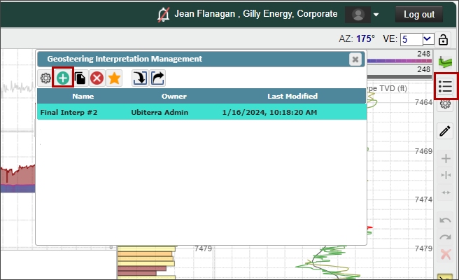
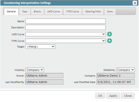
Click the (+) to create a new geosteering interpretation. Here you can also copy, delete, mark favorites, import, and/or export interpretations. A new dialogue box will open, allowing you to designate the name, type curve, LWD curve, target, etc. If you don’t select a target, the interpretation will be hung on the first depth that reaches an inclination of 90 degrees. We recommend assigning a target from your formations in the stratigraphic column. On the Geosteering Interpretation Settings dialog box, you can also add tops, modify your LWD and type curves, view and modify your interpreted strat blocks, and define a target zone.
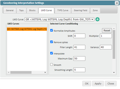
Raw data being received from the WITSML is typically crude and requires proper conditioning. By default, ZoneVu provides similar conditioning to that done by most LWD companies. You must check the radio boxes to activate this conditioning.
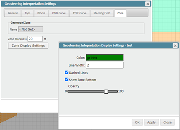
Under the Zone tab, you can set a target zone, if one isn’t already defined from a geomodel. The zone can be color-filled, to appear in the cross-section, and can be used for determining the percent in zone and the distance of the wellbore from top to base of the zone.
Now you are ready to interpret your first stratigraphic block. By default, the entire length of available LWD data is selected. To begin steering the block, click on the GR curve in either the vertical or horizontal track, or click on the colored block directly above the horizontal gr track. The active strat block will be colored red. Again, make sure the Edit Geosteering Block is selected. Note: To adjust the scale of the Vertical Log Track independent of the cross-section, you must have the button selected (it decouples the log track from the seismic x-section).
You can adjust the dip of the block by clicking and dragging the blue (strat block start) and orange (strat block stop) dashed lines on the vertical log track. If you click in between the dashed lines you can bulk shift the strat block up and down, creating a fault. You can also change the dips by clicking on the black squares and diamonds on the cross-section.
To add a new strat block, click the, then click on the location on the horizontal log track where you wish to add a new strat block. Note, you can also splice strat blocks through this method. Hotkey – Hold down CTRL and click the left mouse button on the GR log along the horizontal track to add a new strat block.
To modify a previously created strat block, click on the colored tab of the corresponding strat block directly above the horizontal log track. The active block is red. From here, you can right-click to bring up additional options.
Both the vertical and horizontal log tracks are fully customizable. Logs can be added, removed, and new log tracks can be stacked at the top and left side of the screen, or next to the existing log tracks. To add a new curve, click on the curve name in the Scene Control menu, and drag the curve onto your cross-section. If you drag the curve into an existing curve track, it will be added, if you drag it to a portion of the screen that does not currently have a curve track, a new track will be added.
The software auto-saves, so you don’t need to worry about saving your work if you have computer issues. Also, you can undo interpretations by clicking CTRL + Z.
Viewer "Alt" Keyboard Shortcuts:
Alt + “+”: Zoom In

Alt + “-“: Zoom Out

Alt + Z: Switch Viewers (Map, 2D, 3D, Correlation Panel)

Alt + Q: Opens Display Settings Pop-Up

Alt + A: Opens Scene Control

Alt + I: Opens Scene Info Pop-Up

Alt + X: Opens Scene Snapshot

Alt + S: Opens Measuring Tool

Alt + G: Opens the Geosteering Module

Alt + B: Wellbore Modification Tool

Alt + C: Completions Module

Alt + H: VX/MD Horizontal Scale

Alt + W: Opens Wellbore Notes

Alt + M: Opens the Manual Drilling Update Pop-Up

Alt + R: Opens the Report Generator

Geosteering Hotkeys:
Alt + E: Toggles Edit Geosteering Mode On/Off
CTRL + Z: Undo
CTRL + Y: Redo
CTRL + left mouse button: creates a new geosteering interpretation block for interpretation
Double Left mouse click over a Geosteering Interpretation Block: Activates the Geosteering Interpretation Block (You must be in Active Edit Geosteering Mode)
Right & Left Arrow: With a Geosteering Block selected, each arrow key click will move to the neighboring Geosteering Block in that direction
With the cursor over the Cross-Section:
CTRL + left mouse button: creates a new geosteering interpretation block for interpretation
SHIFT + scroll mouse: Change vertical resolution.
Hold the Left Mouse button: Scroll across the view.
Scroll Mouse: Zoom in/out.
Double Left mouse click over a Geosteering Interpretation Block: Activates the Geosteering Interpretation Block (You must be in Active Edit Geosteering Mode)
Right mouse click over black diamond at start/stop of strat block: Brings up the dropdown menu for various tasks including add block, hide blocks, etc. Also allows you to create/remove a fault.
(In an active interpretation block) Place the cursor over the line depicting the formation top and hold down the left mouse button: The cursor changes to a hand. Hold down the left mouse button and you can adjust the TVD depth of the interpretation block.
Place the cursor over the left or right edge of the interpretation block and hold down the left mouse button: arrow changes to a double arrow. You can change the length of the block.
Hold the left mouse button over a corner of an active strat block: Move the mouse up and down to change the dip of the active interpretation block.
With the cursor over Horizontal Log Track:
CTRL + left mouse button: creates a new geosteering interpretation block for interpretation
Double Left mouse click on a Log: Activates the associated Geosteering Interpretation Block (You must be in Active Edit Geosteering Mode)
Hold the Left Mouse button: Scroll across the view.
Scroll Mouse: Zoom in/out.
Left mouse click on the colored bar above the curve track: Activates the strat block (turns red).
Left or right arrow keys: shift between different active geosteering interpretation blocks (note, the block must be active).
DELETE: Deletes the active interpretation block. You can also right-click on the block and select Delete Block
SHIFT + left mouse hold: adjust the scaling of the type log.
CTRL + Drag Log Header: Moves the log to either a new or existing log track at the top, bottom, or sides of the screen. Three tracks are allowed per portion of the screen.
Scroll Mouse Wheel at the center of the Log Header: Expands or contracts the Min/Max log scale
Scroll Mouse Wheel while over the Log Minimum Value: Changes the Log Maximum Value
Scroll Mouse Wheel while over the Log Maximum Value: Changes the Log Minimum Value
With the cursor over the Vertical Log Track:
CTRL + left mouse button: creates a new geosteering interpretation block for interpretation
SHIFT + Click & Drag Right/Left: Changes the TYPE Log normalization multiplier
CTRL + SHIFT + Click & Drag Right/Left: Changes the TYPE Log normalization shift
Left mouse hold over the center of active interpretation block: Bulk shift the start block up or down
Left mouse click on blue or orange dashed line: Stretch/squeeze interpretation block.
Double Left mouse click on a Log: Activates the associated Geosteering Interpretation Block (You must be in Active Edit Geosteering Mode)
SHIFT + left mouse hold: adjust the scaling of the type log.
CTRL + Drag Log Header: Moves the log to either a new or existing log track at the top, bottom, or sides of the screen. Three tracks are allowed per portion of the screen.
Scroll Mouse Wheel at the center of the Log Header: Expands or contracts the Min/Max log scale
Scroll Mouse Wheel while over the Log Minimum Value: Changes the Log Maximum value
Scroll Mouse Wheel while over the Log Maximum Value: Changes the Log Minimum value
After activating the strat block, press the Delete key: Deletes the active strat block. You can also right-click on the block and select Delete Block.